Png To Stl

Step-by-step guide

Step by step: how to create an stl file out of an image

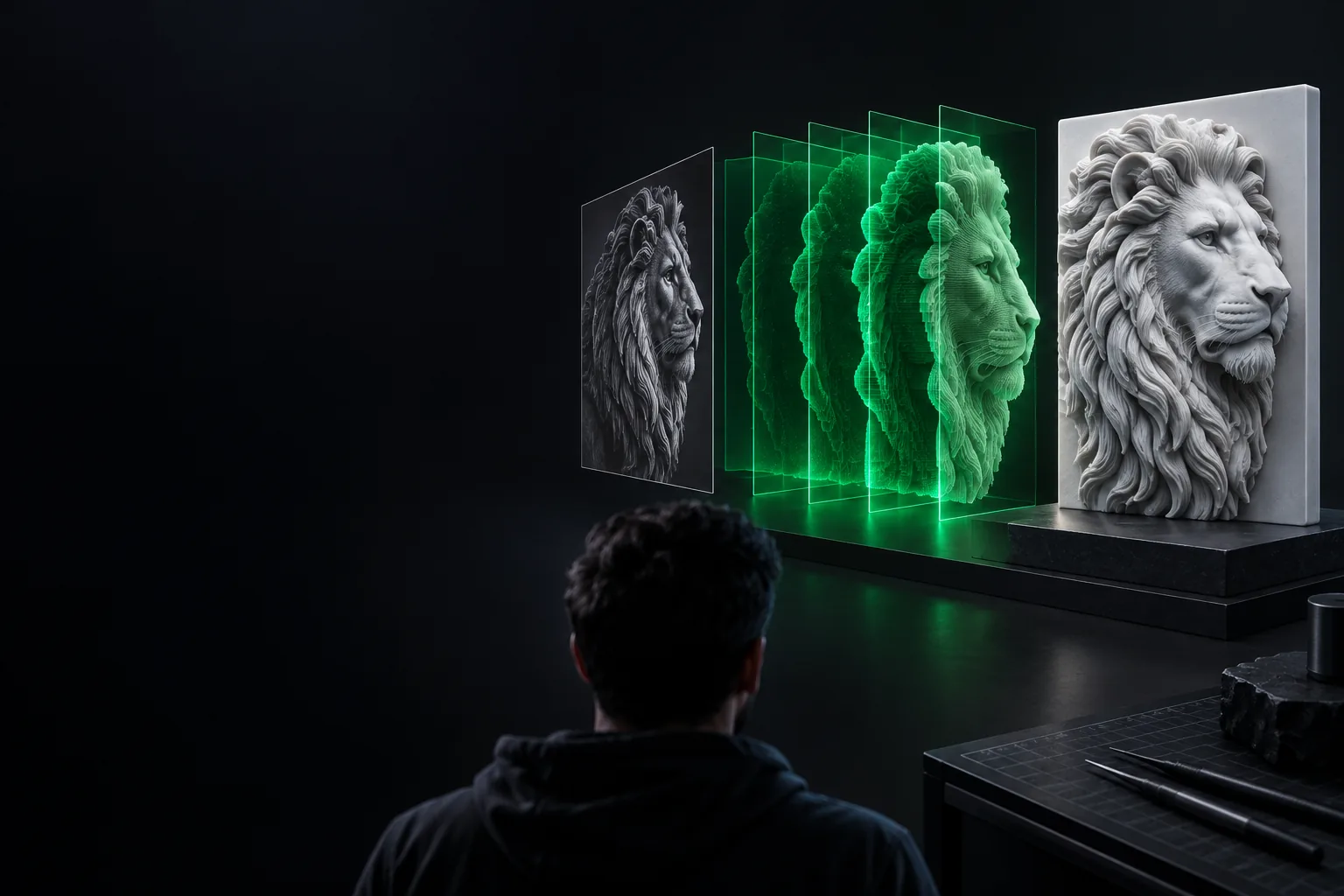
If you are wondering how to create an stl file out of an image, start by deciding what the pixels should become: a raised silhouette, a grayscale relief, or a reference for a modeled object. This guide follows a PNG to STL workflow and shows where to check the mesh before printing.

Describe the shape; check the result
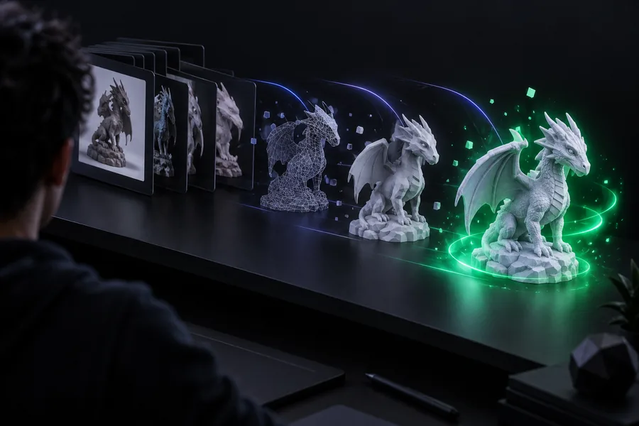
Example 3D form illustrating the transition from a flat image to a model

numbered steps

The short version is to clean the source, give it depth, and validate the exported solid.

  1. 1

    Prepare the picture

    Crop away empty space, increase contrast, and remove stray pixels. For a logo or outline, make the subject distinct from the background; for a relief, retain meaningful grayscale transitions.

  2. 2

    Build the geometry

    Trace a silhouette into closed paths and extrude it, or map grayscale values onto a subdivided surface. Add a base or backing so the resulting shape has printable volume.

  3. 3

    Export and inspect

    Export the finished mesh as STL, open it in a slicer, set its intended dimensions, and inspect every layer for gaps, fragile features, or an unexpectedly inverted shape.

Image and file checklist

Check these inputs before you spend time fixing geometry that began with a poor source.

Required Optional
  • A PNG with a clearly separated subject and background

    Required

    For silhouettes, clean edges matter more than photographic detail.

  • A chosen output style: raised outline or grayscale relief

    Required

    The choice determines whether you trace boundaries or turn brightness into height.

  • A target width and minimum thickness in millimeters

    Required

    Pixels do not supply real-world dimensions to an STL.

  • A mesh editor or image-to-mesh workflow that can export STL

    Required

    Confirm that it can create a closed solid, not just a textured plane.

  • A slicer for previewing the exported mesh

    Optional

    Strongly recommended when the STL will be 3D printed.

The best route depends on whether your starting file contains pixels, paths, or an image you want to edit in a 3D workspace.

From pixels to printable geometry

These three decisions determine whether an image becomes a useful solid or only a flat surface.

Example visual for preparing an image before creating a 3D form

Make the source unambiguous

For a silhouette, remove specks, close gaps, and simplify fine lettering before tracing. A PNG to STL workflow cannot reliably guess whether a faint shadow is part of the object. Inspect the outline at the size you plan to print: tiny islands in the image can become disconnected pieces in the mesh.

SOURCE CHECK

For a two-level plaque, aim for one clear foreground region and one clear background.
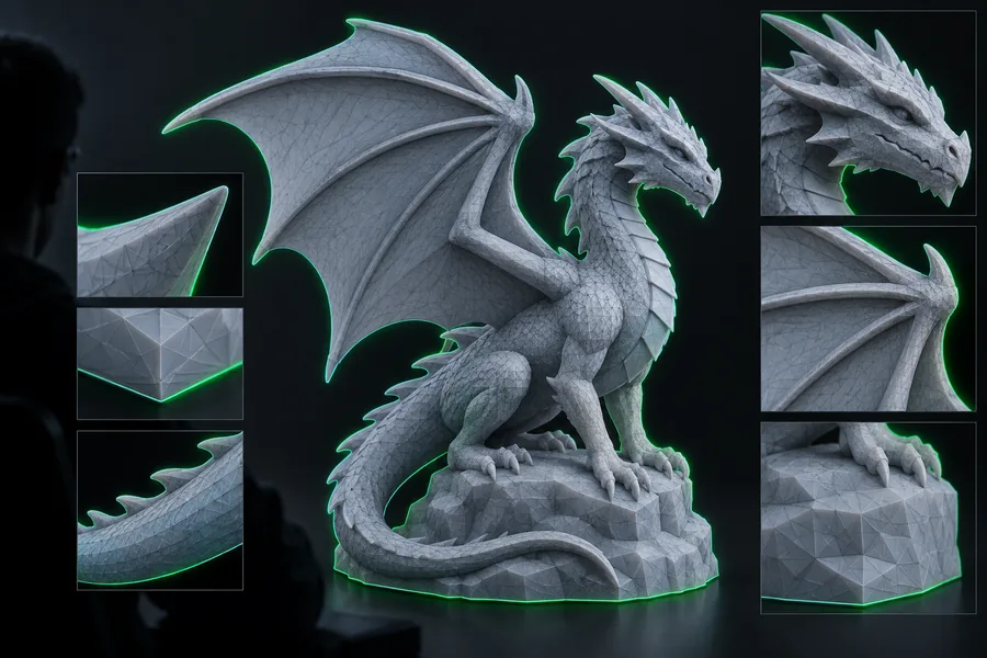
Example visual illustrating depth added to a formerly flat shape

Choose how brightness becomes depth

A black-and-white logo usually works best as traced, closed paths that are extruded to a fixed thickness. A terrain-like or embossed picture needs a different method: subdivide a plane and use grayscale as a height map. Decide whether white or black should be highest, then add a flat backing beneath the relief.

DEPTH RULE

Preview the height direction before export; an inverted map turns raised details into recesses.

Example visual for checking the finished three-dimensional shape

Finish a closed mesh

Apply the intended scale and make sure the object has a top, sides, and bottom. Recalculate face orientation and repair open edges or intersecting pieces before exporting. If you need to know how to create an stl file out of an image for printing, do not stop at the export dialog: open the STL in a slicer and review the layer preview.

FINAL CHECK

A visible model can still contain gaps or surfaces that will not slice as a solid.

Choose a method by image type

The same PNG to STL steps do not suit every picture. Match the modeling method to the information the source actually contains.

Trace and extrude a silhouette

Use a clean, high-contrast logo or icon. Trace its boundary into closed paths, remove unwanted interior islands, then extrude the paths and check that separate shapes are joined where needed.

  • Best for bold lettering, icons, and signs
  • Set physical thickness after tracing
  • Simplify sharp corners that would create fragile tips

Turn brightness into a relief

Use an image with gradual tonal changes to drive height on a sufficiently subdivided surface. Adjust the height range, smooth distracting noise, and add a solid base before exporting the mesh.

  • Best for embossed patterns and terrain-like images
  • Choose which tone represents the highest point
  • Keep a flat back for easier placement and printing

Treat the photo as a reference

A single photograph does not reveal the hidden sides of an object. Isolate a subject for a shallow relief, or model its full shape separately using additional views and measurements.

  • Best for planning or shallow decorative reliefs
  • Do not expect automatic reconstruction of unseen surfaces
  • Check the subject against a known dimension

common errors and fixes

Most failures come from missing depth, ambiguous pixels, or a mesh that looks solid but is not closed.

  • A flat image cannot supply hidden geometry

    A PNG records one view, so PNG to STL conversion cannot infer the back and sides of a photographed object with certainty.

    WorkaroundMake a shallow relief or build the missing surfaces with additional references.

  • Background noise becomes unwanted geometry

    Compression marks, shadows, and stray pixels can turn into bumps or isolated shapes when they are traced or displaced.

    WorkaroundClean the image, simplify its tones, and inspect the traced paths or height map before adding thickness.

  • An STL cannot preserve image color

    Standard STL represents surface geometry rather than the PNG's color channels or transparency.

    WorkaroundUse shape and height to express the design, or choose a color-capable format for a workflow that requires color.

  • A mesh may still be unprintable

    Open edges, zero-thickness surfaces, and features below your printer's practical resolution can fail in a slicer.

    WorkaroundClose the mesh, thicken fragile details, set the intended size, and examine the slicer's layer preview.

advanced tips

The format's history explains several useful choices in a modern image-to-STL workflow.

  1. STL begins as a surface format

    STL emerged for stereolithography and describes an object's surface with triangles. Treat image conversion as a geometry task: the output needs a coherent surface, not merely visible pixels.

  2. PNG provides lossless image data

    PNG 1.0 gave image workflows a lossless raster format. For tracing or displacement, preserve a clean PNG rather than repeatedly saving a source with lossy compression artifacts.

  3. WebGL opens browser-based 3D preview

    With WebGL 1.0, interactive mesh viewing became practical on the web. Rotate a preview to check the sides and underside instead of judging a relief only from above.

  4. Slicer previews remain the last test

    Even when an image-to-mesh workflow feels direct, the final STL still needs a scale and layer check. Previewing toolpaths helps catch thin strokes that looked substantial on screen.

Start with a clear source

Turn a simple image idea into a 3D starting point

Describe the silhouette, intended depth, and flat backing you want to make. Then inspect the resulting geometry, set its dimensions, and check the STL in a slicer before printing.

Create 3D model
  • State which features should be raised
  • Specify a base and approximate thickness
  • Inspect the mesh before printing

tutorial FAQ

Clean the image, then choose whether to trace its outline into an extruded shape or use its grayscale values to create a raised relief. Add thickness and a back, export the closed mesh as STL, and inspect it in a slicer.

Not directly. A clear silhouette or grayscale height map provides useful shape information, but a photo alone cannot reveal an object's hidden sides. Complex subjects usually need manual modeling or additional reference views.

The workflow may have exported a plane or traced outline without adding depth. Extrude the closed outline, or give a displaced surface a solid backing, then inspect the model from the side.

Open it in a slicer, confirm its dimensions, and review the layer preview from bottom to top. Look for missing regions, disconnected pieces, and details too thin for your printer and settings.

Start converting
Start converting